


DXF File for Laser Cutting Custom Acrylic Parts
A clean part can still arrive as a bad file.
Need this made?CNC acrylic machining →
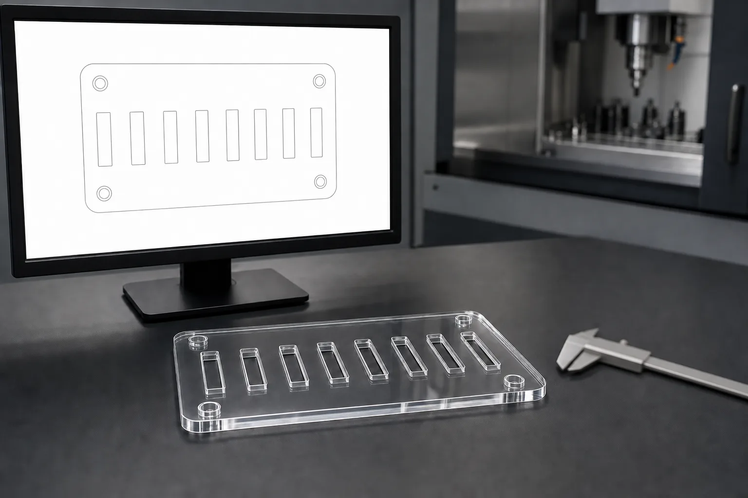
This is the intake standard we run every engineering CAD file through before anything touches a laser or a CNC spindle.
Key Takeaways
- A production-ready DXF file for laser cutting has five properties: closed cut contours, true 1:1 scale in millimeters, cut and engrave geometry on separate layers, no duplicate or construction lines, and text converted to outlines.
- Match the file to the geometry: a DXF drives 2D laser profiles; a STEP file drives CNC machining the moment the part has pockets, counterbores, chamfers, or any feature that is not a through-cut.
- When the CAD file and the written dimensions disagree, neither one silently wins. The order stops, the conflict gets flagged with both numbers side by side, and the buyer's written confirmation becomes the controlling document.
- Tapped holes in acrylic work within limits — cast PMMA breaks at roughly 4% elongation, so threads need coarse pitch and about 2x screw-diameter engagement, and brass inserts beat cut threads for any joint that gets reassembled.
- Tolerance claims should be provable before the batch runs: an annotated approval drawing, a machined sample, and caliper measurement photos keyed to each controlling dimension close the loop without a factory visit.
On this page
- The file that stops a laser line
- The laser-ready DXF checklist
- DXF or STEP: match the file to the geometry
- When the CAD file and the written dimensions disagree
- Controlling dimensions: mark the numbers that must be exact
- Tapped holes and threaded inserts in PMMA
- The measurement-photo proof loop before batch production
- What to send with the file
The file that stops a laser line
Every laser floor has a version of this story: the sheet is loaded, the nest is queued, and the line stops — because the dxf file for laser cutting the job arrived at 1:10 scale with one contour that never quite closes. Nobody drew a bad part; somebody exported a bad file, and that gap costs a day of lead time. The file drives every step of acrylic fabrication, from cutting to inspection.
A production-ready DXF has five properties: closed cut contours, true 1:1 scale in millimeters, cut and engrave geometry on separate layers, no duplicate or construction lines, and text converted to outlines. Send that file with quantity, material grade, and tolerance callouts, and we can normally return an engineering quote within 24 hours.
This guide is the engineering companion to our general custom acrylic RFQ checklist — that page covers the nine commercial fields every quote needs and the no-CAD path from reference photos. This one is for buyers who already have CAD: machine builders, fixture designers, hardware teams sourcing custom PMMA components at our 100-piece MOQ, or a one-off functional prototype ahead of it.
Since 2014, I have seen far more schedule slip caused by file problems than by machine problems, so the sections below walk the file itself — DXF checklist, DXF versus STEP, what happens when the file disagrees with the email, controlling dimensions, threads, and the measurement proof to demand before any batch runs.
The laser-ready DXF checklist
DXF is the exchange format the industry settled on for 2D profiles — a published, plain-text drawing-interchange format that every CAD package exports and every laser nesting suite reads.1 That universality is also the trap: DXF carries no mandatory unit flag, so a millimeter file and an inch file look identical until something measures 25.4x wrong.
Here is the seven-point intake check I run on every incoming cutting file — the same one that works in any CAD package before sending:
| # | Check | Why it stops a line |
|---|---|---|
| 1 | Every cut contour closed | Open contours make the nesting software guess — or reject the path |
| 2 | Units stated, geometry at 1:1 | DXF has no enforced unit; a scale note in the email ends the ambiguity |
| 3 | Cut vs engrave on separate layers | One layer means an operator decides which lines are cuts |
| 4 | No duplicate lines | Stacked segments fire the laser twice — melted edges on acrylic |
| 5 | No construction geometry | Centerlines and guides read as cut paths if left in the file |
| 6 | Text converted to outlines | Font substitution silently reshapes engraved text |
| 7 | Holes drawn as true circles | Polygon-approximated “circles” cut as visible flat facets |
Two of these deserve one more sentence each. On duplicates: a copied-in-place line is invisible on screen, but the beam passes twice and the second pass melts the first edge — on clear acrylic that shows. On closure: a contour open by 0.05 mm still looks closed at any zoom a designer actually works at, which is why I verify closure in software rather than by eye.
Do not compensate for the laser beam’s width in the file. Kerf offset is applied at nesting on the production side, sized to the sheet thickness being cut — draw the part at its finished dimensions and leave the compensation to the shop that knows its machines. If your design pushes tight internal corners or fine engraved detail, our edge-quality guide covers what the beam can and cannot hold on cast PMMA.
DXF or STEP: match the file to the geometry
The split is simple: a DXF describes a flat profile, a STEP file describes a solid. If your part is a through-cut shape — any outline, any thickness, cut straight down — DXF is the right input. The moment the part has a pocket, a counterbore, a chamfer, a stepped profile, or any face that is not full-depth, it is a machining job and the STEP file becomes the working document.
STEP is the neutral 3D exchange standard (ISO 10303-21), built exactly so that product geometry survives the trip between CAD systems without proprietary translation.2 For us it loads straight into CAM programming: the toolpaths come from the actual solid, not from a redrawn interpretation of it. A STEP file for an acrylic part should still travel with a 2D PDF drawing, because STEP carries geometry, not intent — tolerances, finish callouts, and material grade live on the drawing.
Which process a given part actually needs — laser or CNC — is its own decision with its own cost logic, and our CNC vs laser cutting comparison walks that fork properly. For file purposes the rule of thumb holds: 2D geometry, send DXF; 3D geometry, send STEP plus a dimensioned drawing. Send both when a machined part also has profile features the laser will cut first.
One material note for machined parts, and the spec I send back corrections on most often: specify cast PMMA, not extruded. We machine engineering parts from cast sheet because it cuts cleaner under the tool and holds up better through drilling and tapping — extruded sheet is the more brittle, more heat-sensitive grade in a CNC context.
When the CAD file and the written dimensions disagree
It happens more often than any buyer expects: the email says 150 mm, the attached DXF measures 148.5 mm. The file was revised, the text was not — or the other way around. The question that matters is not how it happened. It is which number the factory believes.
Our rule: neither one silently wins. A dimension conflict stops the quote or the job, and we send back one short email with both numbers side by side — “your drawing states 150.0, your file measures 148.5, which governs?” Your written answer becomes the controlling document for the order. The approval drawing is updated to match it, and the file is corrected to the confirmed number before anything is programmed.
I flag these personally on engineering quotes, because the alternative is grim arithmetic: a wrong guess multiplied by a batch is 500 parts that fit nothing, and no inspection step catches a part that was cut faithfully to the wrong number. The 1.5 mm in that example is not a rounding error — it is the difference between a component that seats in the customer’s assembly and one that rattles.
The same logic covers quieter conflicts: a PDF drawing that disagrees with the STEP model it was made from, a revision letter in the filename that does not match the title block, two emails stating two quantities. Anything with two competing values gets surfaced before production, in writing, with both values quoted. Slower by one email, cheaper by one batch.
Controlling dimensions: mark the numbers that must be exact
Not every dimension on a drawing deserves a tolerance — the title-block habit I push back on hardest is the blanket ±0.05 on every line, because buyers who tolerance everything pay for precision nobody needs. A controlling dimension is one where the part stops working if the number drifts — a slot that receives a mating plate, hole centers that must line up with a chassis, an outside width that seats in a channel. Reference dimensions describe the rest of the part; controlling dimensions define whether it functions.
Process capability sets what those tolerances can be. Our standard working tolerance is ±0.2 mm for laser-cut and CNC-machined profiles unless the approved drawing states otherwise, and fit-critical 2D features can be held to ±0.1 mm after drawing review. The precision component project shows why any tighter requirement must name the critical feature, datum, fixture, instrument, and buyer-approved inspection method before quoting. Marking two or three dimensions as controlling, with the tolerance each one actually needs, gets a sharper quote than a title block that blankets every number with the tightest band on the chart.
When marking controlling dimensions, say what they control. “Slot receives 25.0 mm plate, clearance fit” tells our programmer which side of the tolerance to favor. That one phrase does more for the part than a decimal place.
Tapped holes and threaded inserts in PMMA
Buyers sourcing a cad drawing acrylic parts package often include tapped holes drawn exactly as they would for aluminum. The honest answer: acrylic takes threads, but it is not a metal, and the drawing should reflect that. Cast PMMA is stiff and strong in compression, yet it breaks at roughly 4% elongation3 — it does not yield the way nylon or aluminum does. An over-torqued screw in a cut thread strips the crest or splits the boss instead of deforming and holding.
So the feasibility rules we apply at drawing review are conservative and mechanical. Coarse-pitch threads over fine, because the deeper thread form leaves more root material. Thread engagement of about 2x the screw diameter, so the load spreads across enough turns. Hole centers at least 1.5x the hole diameter away from any edge, because a tapped hole near a free edge is where cracks start. And torque specs on the assembly side, snug rather than gorilla-tight.
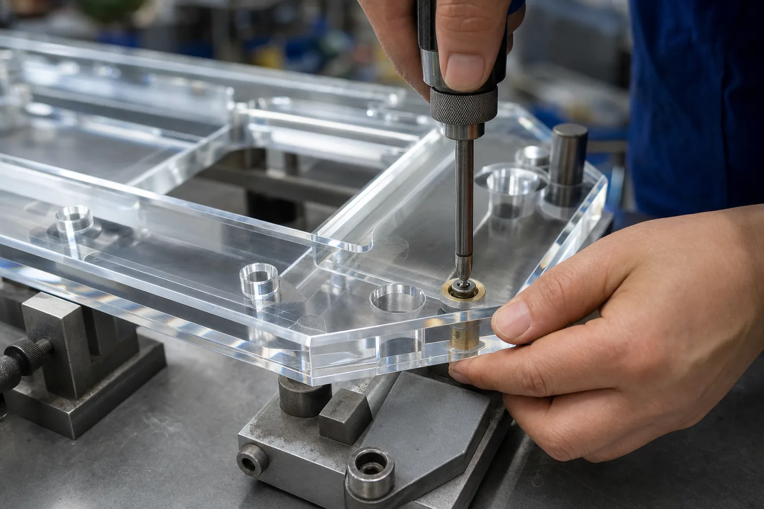
When the joint gets assembled and disassembled more than a few times, we steer the design toward brass threaded inserts — installed into a plain machined bore, the brass takes the thread wear and the acrylic only ever sees compression. For structural joints, a through-bolt with a washer and nut is better still: no threads in the plastic at all, and the washer spreads the clamping load across the surface. All three options come out of the same STEP file; the difference is one line of intent on the drawing.
The measurement-photo proof loop before batch production
An engineering buyer 12 time zones away has a fair question: how do I know the parts meet the drawing before 500 of them ship? The answer should never be “trust us.” It should be a proof loop auditable from a desk on the other side of the world, and this is the sequence we run on toleranced parts:
- Annotated approval drawing. We return your drawing with our production annotations — confirmed dimensions, resolved conflicts, material grade, finish — and you sign off on that document, not on a verbal summary.
- Machined sample. One part (or one per variant) produced in 3-5 days on the same programs the batch will use.
- Caliper measurement photos. Each controlling dimension measured with the caliper in frame and keyed to the drawing callout — slot width photo next to the slot dimension, hole-pattern photo next to the pattern dimension — so you compare number to number, not photo to memory.
- Written acceptance. You confirm the sample, and that confirmation locks the spec for the batch.
- Batch with 100% inspection. Every finished part is inspected against the locked spec before packing — standard on every order in our ISO 9001 system, not an upcharge.
Two practical notes I give every first-time engineering buyer. First, tell us how the protective film should ship — masking on both faces is the default for machined parts, but parts going straight into automated assembly sometimes need film off, and that choice belongs on the drawing. Second, if the part is a functional prototype ahead of a production decision, the same loop runs on a one-off; our prototype-to-production guide covers how a below-MOQ prototype prices and how the sample becomes the QC reference for the eventual batch.
What to send with the file
A complete engineering RFQ for custom acrylic parts is one email: the CAD file (DXF for flat profiles, STEP plus PDF drawing for machined parts), quantity with any tier breaks, material grade — cast PMMA unless there is a reason otherwise — controlling dimensions with tolerances, surface finish per face, the functional context in one sentence, and the target date. That last sentence matters more than buyers think: “this slides against an aluminum rail” or “this seals against a gasket” changes machining and finishing decisions that no dimension captures.
With that packet we quote within 24 hours; samples run 3-5 days and production 15-20 days at our 100-piece MOQ. Components like these end up everywhere in our work — fixture windows, machine guards, instrument bezels, and the structural internals behind our custom display programs — so the odds are good we have machined something close to your part before.
Flagging problems before they reach a laser is the cheapest work we do, which is why your file does not have to be finished to be worth sending. Send the CAD and your controlling dimensions and a quote comes back with any drawing-review flags in the same pass — so you learn what needs changing on your drawing while changing it is still free.
Footnotes
-
AutoCAD Drawing Interchange Format (DXF) Family — Library of Congress format description — documents DXF as Autodesk’s published, ASCII-encoded drawing-interchange format and the de facto standard for 2D CAD geometry exchange, supporting the intake rules in the checklist section. ↩
-
STEP-file, ISO 10303-21 — Library of Congress format description — documents the STEP exchange structure (ISO 10303-21) as the neutral standard for transferring 3D product geometry between CAD systems, supporting the DXF-vs-STEP routing rule. ↩
-
PMMA (Acrylic) — MakeItFrom material properties — displays elongation at break of 4.0% and ultimate tensile strength of 71 MPa for PMMA, the brittleness data behind the tapped-hole and insert guidance. ↩
Frequently Asked Questions
What file format is best for laser cutting acrylic?
DXF is the standard for 2D laser profiles — every mainstream CAD package exports it and every laser nesting suite reads it. Send closed contours at 1:1 scale in millimeters, with cut and engrave geometry on separate layers and text converted to outlines. We also accept AI, EPS, and PDF vector files for graphic work, and a STEP file whenever the part needs CNC machining rather than flat cutting.
What happens if my CAD file and my written dimensions don't match?
Production stops before it starts. We put both numbers side by side in one email — what the file measures and what the text or PDF drawing states — and ask which one governs. Your written answer becomes the controlling document, the approval drawing is updated to match, and only then does the job go to the floor. A silent guess either way is how a factory cuts 500 wrong parts.
Can you tap threads in acrylic parts?
Yes, within limits. Acrylic is stiff but brittle — cast PMMA breaks at roughly 4% elongation — so cut threads strip or split under over-torque instead of deforming. We tap coarse-pitch threads with engagement of about 2x the screw diameter and keep hole centers at least 1.5x the hole diameter from any edge. For joints that get assembled more than a few times, we recommend brass threaded inserts or a through-bolt with a nut instead.
Can I see proof my parts are in tolerance before the batch runs?
Yes — that is the standard sequence, not a special request. You get an annotated approval drawing, then a machined sample in 3-5 days, then caliper measurement photos keyed to each controlling dimension on the drawing so you can compare number to number from your desk. Batch production starts only after your written acceptance, and every finished part passes 100% inspection before packing.
Can you make acrylic parts from a STEP file?
Yes. A STEP file is the preferred input for any machined acrylic part — pockets, counterbores, chamfers, stepped profiles — because it carries the exact 3D geometry into CAM programming. Pair it with a 2D PDF drawing that states tolerances, material grade (cast PMMA for machining), and surface finish. For one-off functional prototypes below our 100-piece MOQ, we quote a prototype premium and a sample-to-bulk path.
Explore Custom Acrylic Products
Browse product categories to compare formats, materials, and customization options before choosing the closest fit for your project.