




Magnets for Acrylic Displays: N35, N42, N52 Hold-Strength Chart
Picking the right magnet for an acrylic display depends on substrate thickness, how the magnet sits in the part and what counter-magnet faces it.
Need this made?Acrylic magnetic photo frames →
Here's how the four variables interact, with published pull-force figures to size against.
Key Takeaways
- Magnet grade alone does not set hold strength — substrate thickness above the magnet face cuts pull force roughly 25-50% across the 3mm to 12mm range, because field strength falls off steeply with air gap.
- An N42 disc embedded flush in 5mm cast acrylic delivers more usable hold than an N52 disc surface-mounted on 8mm acrylic — geometry beats grade once you cross 5mm of substrate.
- Embed mounting keeps the magnet face flush so the air gap stays constant through many open-close cycles; surface-mount loads the adhesive bond line in shear, which is where creep and drift eventually show up.
- Push-fit mechanisms want a 0.3-0.5mm gap to disengage cleanly; pull-fit (concealed) mechanisms tolerate zero gap and are quieter in retail use.
- For products shipping LCL sea freight, design your magnet hold force to roughly 3x the static weight of the part it secures — a common transit-margin rule of thumb for handled goods.
On this page
- What Actually Determines Hold Strength on a Magnet-Mounted Acrylic Part
- Magnet Grades: What N35, N42, and N52 Actually Mean
- Substrate Thickness: Why 3mm Acrylic Limits the Pull You Actually Feel
- Embed vs Surface-Mount: Durability Cycle Comparison
- Counter-Magnet Positioning: Push-Fit vs Pull-Fit
- Vibration and Drop Tolerance for In-Transit Displays
- Putting It Together — A Spec Workflow for Your Next Magnet-Mounted Part
- Related guides
What Actually Determines Hold Strength on a Magnet-Mounted Acrylic Part
Choosing magnets for acrylic displays means sizing an acrylic magnet mount — sometimes called magnetic acrylic in vendor catalogs, or acrylic with embedded magnet when the disc sits flush in the substrate — as a system of four variables: magnet grade, magnet geometry, substrate thickness (how much acrylic sits between the magnet face and the mating surface), and counter-magnet or steel target. Hold strength is set by all four together, not the magnet alone. An acrylic magnetic frame shows the system in its simplest form: two clear panels held together by small neodymium discs at the corners. Across the custom acrylic work we quote, the single biggest mistake we see on inquiry drawings is treating “N52” as the answer when geometry is doing 60-70% of the work.
Most buyers spec a magnet from a vendor catalog rated at face-to-face contact — say, 8 lbs of pull on a 12mm × 3mm N42 disc — then put 5mm of acrylic in between and wonder why their lid feels loose. The catalog number assumed a zero air gap and a steel plate as the target. Push that disc into the back of an acrylic case so its face sits 5mm below the top surface, and the effective pull at the surface falls to a fraction of the catalog rating. Add another 0.5mm of paint, label, or the top of the mating part and it drops further still. That’s not a defective magnet; that’s how magnetic field strength falls off with distance — a relationship you can read straight off a supplier’s pull-force-vs-gap curve, such as the ones K&J Magnetics publishes1.
This guide walks the four variables with published pull-force data — N35, N42, and N52 grades crossed against 3, 5, 8, and 12mm cast acrylic substrate — plus the embed-versus-surface durability tradeoff, and the counter-magnet rules for push-fit and pull-fit mechanisms. The goal is a spec table you can hand to your industrial designer, plus the reasoning so you can make tradeoffs the table doesn’t pre-tabulate.
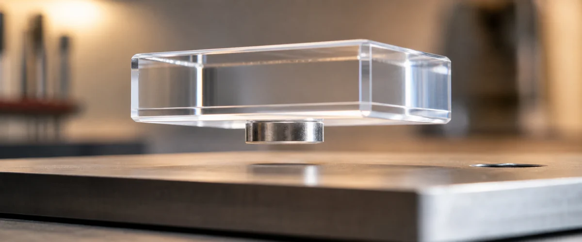
An N42 disc embedded in 5mm cast acrylic about to mate with a steel base plate. The few millimeters of air gap visible here is exactly what controls usable pull force in real product use.
Magnet Grades: What N35, N42, and N52 Actually Mean
Neodymium magnet grades are labeled by their Maximum Energy Product (BHmax), measured in megagauss-oersteds (MGOe). N35 is roughly 35 MGOe, N42 is 42 MGOe, N52 is 52 MGOe. Higher BHmax means more usable magnetic energy in the same volume — which translates roughly, but not linearly, into more pull force. The grade scale is the standard NdFeB classification published by Arnold Magnetic Technologies2; the underlying magnetic property test methods are codified in ASTM A9773.
In practical B2B fabrication terms: N35 is the bottom of the commercial catalog and shows up mostly in entry-tier consumer goods. N42 is the workhorse — predictable, widely stocked, and the default neodymium acrylic spec for industrial and display applications. N52 is the highest commercially available grade, costs roughly 2x N42 per piece, and is more brittle and more vulnerable to corrosion if the nickel-copper-nickel plating fails. For an acrylic magnet mount, I specify N42 on roughly 80% of orders, N52 only when a thin substrate plus a hidden mount geometry needs every gram of pull, and N35 essentially never — the savings don’t justify the variance.
The pull force ratio between grades on the same physical disc is roughly N35 : N42 : N52 = 1.00 : 1.20 : 1.34, tracking the ratio of their residual induction (Br) values in published NdFeB grade data. That ratio is broadly consistent across common disc sizes (12mm × 3mm, 15mm × 3mm, 20mm × 5mm). Note this is a ratio of pull forces for identical geometry — if you upsize from a 12mm × 3mm N42 to a 20mm × 5mm N42, pull force can roughly triple from grade-and-size combined, which is usually a more cost-effective move than chasing N52.
Magnet grade comparison at standard B2B disc sizes
| Disc Size | N35 Pull (lbs) | N42 Pull (lbs) | N52 Pull (lbs) |
|---|---|---|---|
| 10mm × 2mm | 2.1 | 2.5 | 2.8 |
| 12mm × 3mm | 4.0 | 4.8 | 5.4 |
| 15mm × 3mm | 5.4 | 6.5 | 7.3 |
| 20mm × 5mm | 11.2 | 13.5 | 15.0 |
Figures are typical catalog pull values for face-to-face contact against a steel plate at zero air gap — the way suppliers such as K&J Magnetics1 publish them. Treat them as approximate; actual pull varies with plating, exact target thickness, and temperature. Critically, they will not represent what you feel through 5mm of acrylic. That’s what the next section is for.
Substrate Thickness: Why 3mm Acrylic Limits the Pull You Actually Feel
The defining number for any acrylic magnet mount is the distance between the magnet face and the mating surface — the effective air gap. Magnetic flux density falls off rapidly with distance from the magnet face; in the near field that drop-off is steep enough that adding 2mm of cast acrylic between magnet and target can cut usable pull by 30-40%. A 3mm acrylic layer is about the practical maximum before pull force degrades enough to feel “weak” in the hand — which is why on lids and hinge covers we usually ask buyers to either embed the magnet from the back side or step up to a larger disc.
Cast acrylic is not magnetically active — PMMA’s relative permeability is essentially 1.0, the same as air. So the substrate doesn’t block the field, it just separates the magnet from the steel or counter-magnet on the other side. The pull-force degradation curve is geometric, not material-dependent. This is good news for design: you can sometimes machine away local material — a counterbore on the back side of the lid, for example — to shorten the effective air gap without changing the visible front face. We do this often on premium retail lids where the buyer wants a clean unbroken acrylic top but needs a strong latch.
Hold Strength Spec Chart — Pull Force (lbs) by Grade × Substrate Thickness
The table below estimates pull for 12mm × 3mm discs of each grade through cast acrylic spacers of the indicated thickness, derived from published pull-force-vs-gap behavior1 — cast acrylic (PMMA) is magnetically inert, so it acts purely as air-gap spacing. The “0 mm” column is the magnet face contacting the steel target directly (no acrylic in between). The “0.5 mm” column adds an additional 0.5mm air gap to account for real-world clearance, paint layers, or labels — this is the number to use for production sizing.
| Substrate Thickness | N35 — 0 mm gap | N35 — 0.5 mm gap | N42 — 0 mm gap | N42 — 0.5 mm gap | N52 — 0 mm gap | N52 — 0.5 mm gap |
|---|---|---|---|---|---|---|
| 3 mm cast acrylic | 5.2 lbs | 4.0 lbs | 6.3 lbs | 4.8 lbs | 7.0 lbs | 5.4 lbs |
| 5 mm cast acrylic | 4.0 lbs | 3.0 lbs | 4.8 lbs | 3.6 lbs | 5.4 lbs | 4.0 lbs |
| 8 mm cast acrylic | 2.7 lbs | 2.0 lbs | 3.2 lbs | 2.4 lbs | 3.6 lbs | 2.7 lbs |
| 12 mm cast acrylic | 1.4 lbs | 1.0 lbs | 1.6 lbs | 1.2 lbs | 1.8 lbs | 1.3 lbs |
Reading the table: an N42 12mm × 3mm disc behind 5mm of cast acrylic delivers 3.6 lbs of usable pull with a half-millimeter clearance gap. That’s a comfortable hold for a lid or door weighing up to about 200g. The same disc behind 12mm of acrylic drops to 1.2 lbs — borderline acceptable for a light cover, undersized for any latch you expect to feel “snappy”. This is also why the practical answer to “how thick can the acrylic be before the magnet stops working” is roughly 8mm before you start needing a deliberate workaround.
For more on how cast acrylic thickness interacts with fabrication, see our acrylic thickness guide — and for the cast versus extruded decision at thicker substrates, see cast vs extruded acrylic, since extruded sheet has worse thickness consistency that propagates straight into pull-force variance on a magnet mount.
Embed vs Surface-Mount: Durability Cycle Comparison
There are two ways to attach a magnet to an acrylic part: embed it (machine a pocket, seat the magnet flush, bond) or surface-mount it (bond the magnet to the back face with adhesive). Embed is cleaner-looking and more durable. Surface-mount is faster to assemble, lower-cost, and easier to retrofit. The tradeoff most buyers miss in their first inquiry is the cycle-life difference — how many open-close events the joint survives before the bond drifts, the magnet pops out, or the hold strength degrades.
The two configurations differ in where the mechanical load lands. In an embed mount, the magnet seats in a milled pocket and its face is flush with the acrylic; every open-close event drives the magnet straight into the target in compression, and the bonded interface behind it is loaded in compression too. In a surface mount, the magnet is bonded to the back face and the closing pull tugs the adhesive layer in shear each cycle. That difference is what governs durability.
Why embed outlasts surface-mount over repeated cycles
| Failure driver | Embed mount | Surface mount |
|---|---|---|
| Working air gap | Fixed at the flush-face clearance — stays constant as the part cycles | Full substrate thickness plus clearance — larger and constant, but the bond behind it is what wears |
| Bond-line loading | Compression (favorable) — adhesives are strong in compression | Shear each cycle (unfavorable) — where creep and eventual debonding start |
| Typical failure mode | Cosmetic plating scuff where the face meets the steel target | Bond creep, magnet drift/rotation, and adhesive fatigue over time |
| Practical takeaway | Hold force stays steady over long cycle life | Fine for low-cycle use; degrades as cycle count climbs |
Adhesive creep and fatigue under sustained shear are well-documented behaviors of structural bonds — the reason bonded joints are designed to load adhesives in compression or shear-with-area rather than peel. That’s the mechanism behind the difference: embed mounts keep the joint in compression, so hold force stays steady; surface mounts put it in cyclic shear, where general-purpose acrylic adhesives eventually creep. We use a stiff two-part epoxy for surface-mount when embedding isn’t possible, but for any product expected to cycle more than a few thousand times — retail display lids, sample case latches, presentation box hinges — embed is the right call. For lids or bases where a back-side pocket is not possible, see the embed and surface-mount options on our acrylic display pedestals page.
Practical decision rule: if the part will see fewer than 1,000 open-close cycles in its working life (one-time presentation kits, single-event displays), surface-mount is fine and saves cost. If it will see 5,000+ cycles (anything that opens daily for a year+), embed is worth the extra fabrication step. Embedding adds roughly $0.50-$1.50 per magnet depending on quantity and pocket complexity — a small price relative to the field failure cost.
Counter-Magnet Positioning: Push-Fit vs Pull-Fit
Once you’ve sized the magnet and chosen the mount style, the next decision is what the magnet pulls against. Two patterns dominate B2B acrylic work: push-fit and pull-fit. They feel different in the hand, fail in different ways, and need different counter-magnet geometry. Mixing them up is the second-most-common spec mistake I see, after grade-only magnet sizing.
Push-fit mechanisms use a magnet on each side that snaps the lid or door closed at a specific gap and disengages with a deliberate push. The user feels a tactile click. We typically pair an N42 12mm × 3mm disc on one side with an N42 8mm × 2mm counter-magnet on the other, with a 0.3-0.5mm air gap at closed position. The smaller counter-magnet limits the closing pull, while the air gap prevents binding under temperature and humidity changes. Push-fit is the right pattern for a magnet acrylic display lid customers open repeatedly, presentation case doors, and anything requiring a clean visual seam.
Pull-fit (sometimes called “concealed pull”) uses one magnet on the moving part and a steel plate or large recessed magnet on the fixed part, positioned so the user grips a hidden edge and pulls against a strong holding force. There is no tactile click — the part either holds firmly or comes free. Counter-magnet can be the same size and grade as the primary, with zero air gap at closed position. The mechanism is quieter, holds more weight, and is harder to defeat by accident — the default for permanent installations and premium showcases. The same pattern works as a concealed catch on a wall mounted acrylic display case, where the cover should stay closed without visible hardware.
Push-fit vs pull-fit — typical positioning behavior (N42 paired discs, 5mm cast acrylic substrate)
Figures below are representative for the geometry described, to show the relationship between air gap, closing force, and holding force — not a measured dataset. Size your own parts against supplier pull-force curves1 for the exact discs you specify.
| Configuration | Closing Force | Holding Force | Tactile Feel | Best For |
|---|---|---|---|---|
| Push-fit, 0.3 mm air gap | ~2.8 lbs | ~4.4 lbs | Soft snap | Retail lids, sample boxes |
| Push-fit, 0.5 mm air gap | ~2.0 lbs | ~3.6 lbs | Light click | High-cycle daily-open parts |
| Pull-fit, 0 mm gap (matched magnets) | ~4.8 lbs | ~4.8 lbs | Silent firm hold | Premium showcases, permanent installs |
| Pull-fit, 0 mm gap (steel target) | ~3.4 lbs | ~3.4 lbs | Silent moderate hold | Wall mounts, lower-cost concealed |
Closing force is what the user feels when the part is about to mate — too high and it snaps shut painfully, too low and the part doesn’t self-align. The 0.3-0.5mm range is the comfortable zone for most retail and presentation work. For pull-fit, where there’s no air gap by design, the holding force IS what the user feels when they pull the part off, so size it to the part’s actual handling weight times 3 minimum.
Vibration and Drop Tolerance for In-Transit Displays
A magnet-mounted acrylic part that holds firmly by hand can still separate during international freight if the design margin isn’t right. The transit hazards are random vibration and repeated shock — the same conditions that transport-simulation standards are written around, including ASTM D41694 (distribution-cycle testing) and the ISTA5 packaged-product series that simulate common-carrier truck and ocean handling. Sizing hold force with those hazards in mind is what keeps a part together on ocean LCL freight, the most common journey our parts make.
The headline rule of thumb for handled goods: design the static holding force to roughly 3x the part’s weight for LCL sea freight, 2x for air freight, and 5x for any part mounting overhead or to a vehicle. Below about 2x, parts start separating in transit; below 1.5x we won’t quote the part — it fails in shipping and gets remade on our cost. As a final check before a shipment goes out, we do a simple in-house drop-check on a loaded sample case to confirm nothing has worked loose. For the broader manufacturing context, see how acrylic products are made; for substrate selection, our acrylic blocks and embedded-element work.
Transit-margin guidance across mount configurations
The table maps common configurations to the hold-force-to-weight ratio they produce and where that lands relative to the 3x LCL rule of thumb above. It’s design guidance for sizing, not a test log.
| Mount Configuration | Static Hold / Part Weight Ratio | Margin vs 3x LCL rule | Guidance |
|---|---|---|---|
| N42 embed, 5mm acrylic, 200g lid | 24x | Far above | Massive margin — could downsize magnet |
| N42 embed, 8mm acrylic, 400g lid | 8x | Well above | Good production spec |
| N42 surface-mount, 5mm acrylic, 300g lid | 12x | Well above | Good for low-cycle use |
| N35 surface-mount, 5mm acrylic, 400g lid | 8x | Above, but thin margin on a weak grade | Step up to N42 for headroom |
| N42 embed, 12mm acrylic, 800g lid | 1.5x | Below — under the 2x floor | Reject — needs larger magnet or back-side counterbore |
The last row is the failure mode we see most often on first-pass buyer drawings: a thick acrylic top and a heavy mating part with a magnet sized from the catalog face-to-face number. The math looks fine on paper and a hand check feels solid, but the effective air gap through 12mm of substrate leaves too little margin for transit shock. The fix is usually one of three moves: machine a back-side counterbore to shorten the effective air gap, upsize to a 20mm × 5mm disc, or move from an open-pocket embed to a fully encapsulated embed where the bond line carries some of the shear load. We work all three options into the spec review at quote stage.
Putting It Together — A Spec Workflow for Your Next Magnet-Mounted Part
When a buyer sends me a drawing for a magnet-mounted acrylic part, I work through it in this order: (1) part weight and orientation, (2) substrate thickness and which side the magnet sits on, (3) cycle expectation, (4) push or pull mechanism, (5) freight mode. Each answer narrows the magnet spec. Most parts converge on N42 12mm × 3mm or N42 15mm × 3mm with embed mounting and a 0.3-0.5mm push-fit gap — that combination cleanly covers about 70% of B2B retail and presentation work.
Cases where you should push back against a default spec: anything overhead (use 5x weight ratio), anything shipped in a hard-sided sample case to a trade show (vibration profile is harsher than truck freight), anything thicker than 8mm of substrate (consider a back-side counterbore or a larger disc), and anything where the visible front face can’t have any magnet shadow (some plating shows faintly through thin clear acrylic — switch to an opaque or frosted backer or move to a recessed embed).
If you have a part in development and you’re not sure whether your acrylic magnet mount spec will survive the journey, send the drawing to inquiry@wetopacrylic.com or use the contact form. We’ll review the geometry, recommend a grade and mount style based on the sizing logic above, and quote the magnet sourcing and embed step separately so you can see what each spec choice costs. Sample lead time for a magnet-mounted prototype is 5-7 days from drawing approval; production runs land in our standard 15-20 day window.
Our magnetic acrylic components project shows the workflow for drawing control, polarity checks, first-article approval, and protective packing.
Related guides
Footnotes
-
K&J Magnetics — pull-force data and calculators for neodymium disc magnets — a widely used reference for published pull-force ratings by grade and geometry, plus pull-force-vs-air-gap curves. Useful for sizing before you account for the acrylic substrate as air-gap spacing. ↩ ↩2 ↩3 ↩4
-
Arnold Magnetic Technologies — Neodymium Iron Boron (NdFeB) magnet grades and properties — major North American producer of rare-earth permanent magnets; their published grade reference covers BHmax, residual induction, coercivity, and operating temperature ranges for the full N35-N52 commercial range we source against. ↩
-
ASTM A977 / A977M — Standard Test Method for Magnetic Properties of High-Coercivity Permanent Magnet Materials — the standardized hysteresisgraph method for measuring BHmax, residual induction (Br), and coercivity (Hc) of sintered NdFeB and similar permanent magnet materials. Grade classification claims for our magnet sourcing reference this test. ↩
-
ASTM D4169 — Standard Practice for Performance Testing of Shipping Containers and Systems — the standard distribution-cycle method (vibration, shock, compression) used to simulate the hazards a packaged product meets in truck and ocean transit. ↩
-
ISTA (International Safe Transit Association) — packaged-product test procedures — industry test series (e.g., 3A, 3E) simulating common-carrier and ocean-freight handling, vibration, and drop hazards for shipped goods. ↩
Frequently Asked Questions
What size neodymium magnet do I need for a 5mm acrylic display lid?
For a typical retail display lid weighing under 200g on 5mm cast acrylic, a 12mm diameter × 3mm thick N42 disc embedded flush gives roughly 4-5 lbs of pull at face contact against a steel target — around 10x the static weight, which is the safety margin we recommend for products that ship internationally and get handled daily in store. Published pull-force figures from magnet suppliers such as K&J Magnetics are a good starting point for sizing before you account for the air gap.
Is N52 always better than N42 for acrylic mounts?
No. N52 has roughly 12% higher pull force than N42 at the same dimensions, but it's also more brittle, more expensive, and more prone to corrosion if the nickel plating chips during recessing. For most B2B acrylic displays at 3-8mm substrate, N42 is the better choice — predictable hold, lower unit cost, and once the magnet is embedded flush it holds its strength through repeated open-close cycles because the field-facing air gap never changes.
Can you embed magnets inside cast acrylic during fabrication?
Yes. We pocket-mill a recess into the cast acrylic at the CNC stage sized to the magnet's measured outer diameter and marked fit-critical on the drawing (±0.1mm after drawing review), then bond the magnet in with a two-part epoxy rated for non-magnetic encapsulation. The magnet face sits flush with the acrylic surface, which preserves the optical line and protects the nickel plating from edge impacts during transit.
How thick can the acrylic be before the magnet stops working?
Pull force falls off steeply with the air gap, so substrate thickness matters more than most buyers expect. As a rule of thumb, an N42 12mm × 3mm disc that gives roughly 4-5 lbs at face contact can drop to under 2 lbs once you put 12mm of acrylic between the magnet and the mating surface — still useful for a light cover, but inadequate for anything that latches under load. Above 8mm we usually recommend embedding the magnet from the back side so it sits closer to the mating surface. Supplier pull-force-vs-gap curves (for example from K&J Magnetics) show the same falloff you'll feel in the finished part.
Do magnet-mounted acrylic displays survive international freight?
Yes, when the design is sized correctly. The transit hazards that separate magnet-mounted parts are vibration and shock — the same conditions addressed by transport-simulation standards like ASTM D4169 and the ISTA packaged-product test series. A magnet hold force of roughly 3x the part's static weight is a sound margin for handled goods on ocean LCL freight; below about 2x, parts start separating in transit, so we won't ship a magnet-mounted design under that margin without a spec change. Before shipping we do a simple in-house drop-check on a loaded sample case to confirm nothing works loose.
Need a spec quote on a magnet-mounted acrylic part?
Send us your design with the part weight, the surface it mounts to, and how often it opens. We'll size the magnet grade, recommend embed vs surface, and quote the cast acrylic and assembly together — usually inside 24 hours.